Download the lastest release and extract the files into any directory. Read the README file in that folder.
Windows 9x/2000 users must have ActiveState ActiveTcl 8.4 or higher installed in their machine to use this tool. The application can be started by double clicking on the file “dfdeditor.tcl”.
Linux users must have Tcl/Tk 8.1 or higher with iTcl/iTk installed. The application can be run by simply executing the same file from the command prompt in a X terminal.
On invocation the application window opens with a blue drawing canvas, a toolbox at the left of the canvas, a menubar and a toolbar. At this stage, the “Hands Free” option in the toolbox is seen as selected. This means that “no drawing tool is selected” at the moment, i.e. the system is in “Hands Free” mode. At a later stage you can go to the "Hands Free" mode by pressing the "Escape" key from the keyboard.
We offer you four basic symbols to draw a DFD - process, external entity, data store and data flows. We expect that you know how to draw a correct DFD.
To draw a DFD you can follow these steps :
1. Click any button in the toolbox of the application window except "Data Flow" button. At this point the cursor changes to reflect the shape of the selected symbol.
2. Click on the drawing canvas to place the item you have selected.
3. Once you click a button, it remains suppressed, to show which item you can currently draw. You can click other buttons to draw all other items.
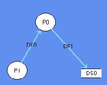
4. Now click the "Data Flow" button. To draw a data flow between two items, click on ITEM0 and then on ITEM1 to see an arrow appear between them directed towards ITEM1. Certain restrictions have been forced for drawing data flows by keeping various checks on the source and destination of the data flows.
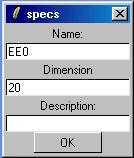
5. You can change the name & size of an item and can add some description to them. To do this, make sure you are in the the "Hands Free" mode. Now right-click on a item (i.e. Symbol) to bring a popup window like the following where you can change its name & size and also add some description. Now clicking "OK" will store these properties for that item. After that if you roll the mouse pointer over the symbol, its description is shown in the status bar of the application window. The following figure shows the popup window for external entities and data stores.
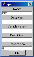
The popup window for data flows will be like the following image. The Data type, Variable names and sequence number fields will be discussed later.
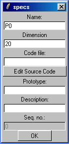
The popup window for process bubbles will be like the following image. The Code file, Prototype and Seq no. fields will be discussed later.
6. To draw the next level DFD for any process, make sure you are in the "Hands Free" mode. Now double click on any of the processes on the DFD. The canvas will be cleared up and you can draw a detailed DFD for the process you selected.
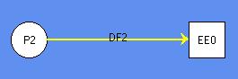
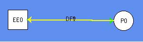
Different data flows in a DFD will have different colors depending on the elements between whom the data flows. The significance of the colors of the data flows is shown in the following images.
Any external flow to a process will be colored green.
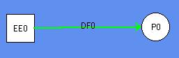
Any internal flow of a DFD will be light blue.
Finally, any external flow from a process will be yellow.
How to delete a symbol from a DFD?
You have to be in "Hands Free" mode to delete any element from a DFD. Click on the element to be deleted. It changes its outline, which means it is selected. Now press "Delete" key from keyboard to delete the element after confirming your action. You can also press Shift+Delete to delete the selected element without confirmation.
Remember that if you delete a process which had at least another level of detailed DFD, then all the levels of detailed DFDs for that process will be deleted. Other processes will not be affected.
How to move to an upper level of a DFD?
Click on the "Uplevel" button at the left-bottom corner of the application window or simply press the "PageUp" key from the keyboard.. You will reach the immediate upper level DFD. You can go on doing the same untill you reach Level0 DFD.
Validating a DFD means checking whether all its levels are balanced with respect to the data flows. Unbalanced flows will be shown by coloring them red.
You can even see a validation report in HTML format by clicking the "Generate Report" button on the toolbar.
To
save a DFD into the file system at any folder, either click File>Save from
the menubar or the "Save File" ![]() button on the toolbar. You will be asked to enter a file name for the DFD. The
default extension of such a file will be ".dfd". The default location
of the file will be the working directory. If your DFD was already assigned
a file name, then the changed DFD will be automatically saved into that file.
button on the toolbar. You will be asked to enter a file name for the DFD. The
default extension of such a file will be ".dfd". The default location
of the file will be the working directory. If your DFD was already assigned
a file name, then the changed DFD will be automatically saved into that file.
How to load a DFD into the canvas?
To load a DFD into the canvas from a file, either click File>Load from the menubar or the "Load File" on the toolbar. You will be asked to select a file which contains a DFD, which will be shown on the canvas. All the levels of the DFD will be available.
You
can click File>Print from menubar or the "Print" ![]() button on the toolbar to print the DFD shown the canvas. The print dialog box
will open, which will let you select the page size and destination of the shown
DFD. If you choose the destintion as Printer and click the "Print"
button on the dialog box, the DFD will be sent to your printer. Alternatively,
you can select the destination to be a PostScript (.ps) file. You have to open
the PostScript file separately with a standard PostScript viewer like GS View
and print it from there.
button on the toolbar to print the DFD shown the canvas. The print dialog box
will open, which will let you select the page size and destination of the shown
DFD. If you choose the destintion as Printer and click the "Print"
button on the dialog box, the DFD will be sent to your printer. Alternatively,
you can select the destination to be a PostScript (.ps) file. You have to open
the PostScript file separately with a standard PostScript viewer like GS View
and print it from there.
Just
click on the "Zoom in" ![]() or "Zoom out"
or "Zoom out" ![]() button on the toolbar to zoom and shrink the DFD on the canvas respectively.
The zoomed or shrinked DFD can not be saved in the file. To increase the size
of the DFD elements, you have to right click on the element (while in "Hands
Free" mode) and change the "Dimension" foeld from the pop-up
"specs" window.
button on the toolbar to zoom and shrink the DFD on the canvas respectively.
The zoomed or shrinked DFD can not be saved in the file. To increase the size
of the DFD elements, you have to right click on the element (while in "Hands
Free" mode) and change the "Dimension" foeld from the pop-up
"specs" window.
At first you have to shift to "Hands Free" mode. Now just drag the DFD element to be moved by pressing the left mouse button. Release the element at any position on the canvas.
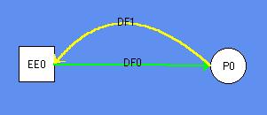
Two items may have two way data movement. To express this kind of data flow you have to draw two data flows in opposite direction, one above the other. This might look confusing. What if you could visibly separate these flows? To separate two diffrent but overlpping data flows, just drag one of them. The dragged data flow will curve out.
The following pictures show how it happens.
If
you want to undo any operation on any level of the DFD, just click the "Undo"
![]() button on the toolbar. You
can continue to click on the button to undo other previous operations starting
from the last one.
button on the toolbar. You
can continue to click on the button to undo other previous operations starting
from the last one.
How to insert code into process bubbles?
You have to bring the "specs" pop-up window by right-clicking (while you are in "Hands Free" mode) on any process bubble. On the "specs" window Click the "Edit Source Code" button. An editor opens up, where you can type the function code. You can save the function in a file by clicking on the menu File>Save or the "Save" button on the toolbar of the editor window. You will be promted to enter the file name. Coming back to the "specs" window you can enter the prototype of the function in the "Prototype" textbox.
The datatype and variable name of the information flowing through a data flow can be specified in the "specs" window for that data flow. As before, right-clicking on any data flow will show its "specs" window. Now you can fill up the "Data type" and "Variable name" fields.
The datatypes of the arguments to the function of a process should match the datatypes of its inflows. Similarly, the return type of a function should match the datatypes of its outflows.
How to generate top level code?
After
entering the prototypes of the functions and datatypes of the data flows, you
are ready to generate a top level code which will bind these functions in propar
sequence. To generate this code you have to click the "Generate Code"
button at the left corner of the applcation window. If there is a mismatch between
the datatypes of the flows and those of the function prototypes, it will be
shown as an error message. Otherwise, you will be promted to enter a file name
to save the generated top level code. Then the contents of the file will be
shown in an editor window.
We are a group of students pursuing M.Tech in Computer Science and Engineering at the University of Calcutta.
Soumava Das [ soumava@acm.org ]
Avishek Thakur [ avishekt@yahoo.com ]
Tanumoy Bose [ tanumoyb@yahoo.com ]